The macadamia industry is growing amid a rapidly changing world. What worked yesterday might not work tomrrow. Delivering a high quality product to broad base of comsumers is imperative to maintaning prices. And continuous growth in consumption requires continuous innovation.
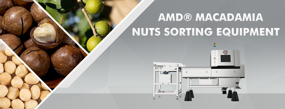
With leading multi-spectral detection technology, AMD® sorters provide superior detection capabilities to help you eliminate defects in macadamia nuts and ensure consistent food safety.
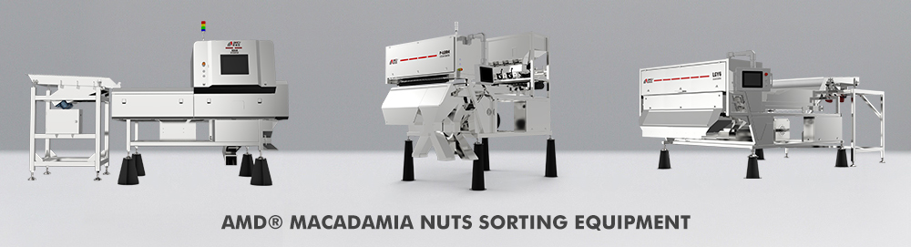
AMD has introduced a comprehensive inspection and sorting solution for the macadamia nut industry. This solution is applicable to both external and internal inspection of inshell macadamia nuts, as well as color and shape sorting of macadamia kernels, among other functions, assisting enterprises in enhancing both the yield and quality of their products.
INSHELL MACADAMIA NUTS SORTING
External Sorting
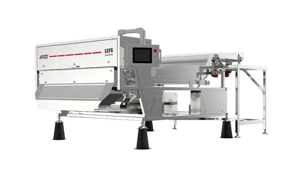
AMD® LGY Series Belt-type Optical Sorting Machine can replace manual work and accurately identify the defects of shelled macadamia nuts including obvious breakage, abnormal colour spots, dirty nuts, mold filaments and other substandard products.
Based on visible light technology, the AMD® LGY offers processors the flexibility of sorting different varieties and grades of macadamia nuts in-shell, whole, halves, and pieces.
AMD® LGY Inshell Macadamia Nuts Color Sorting Machine
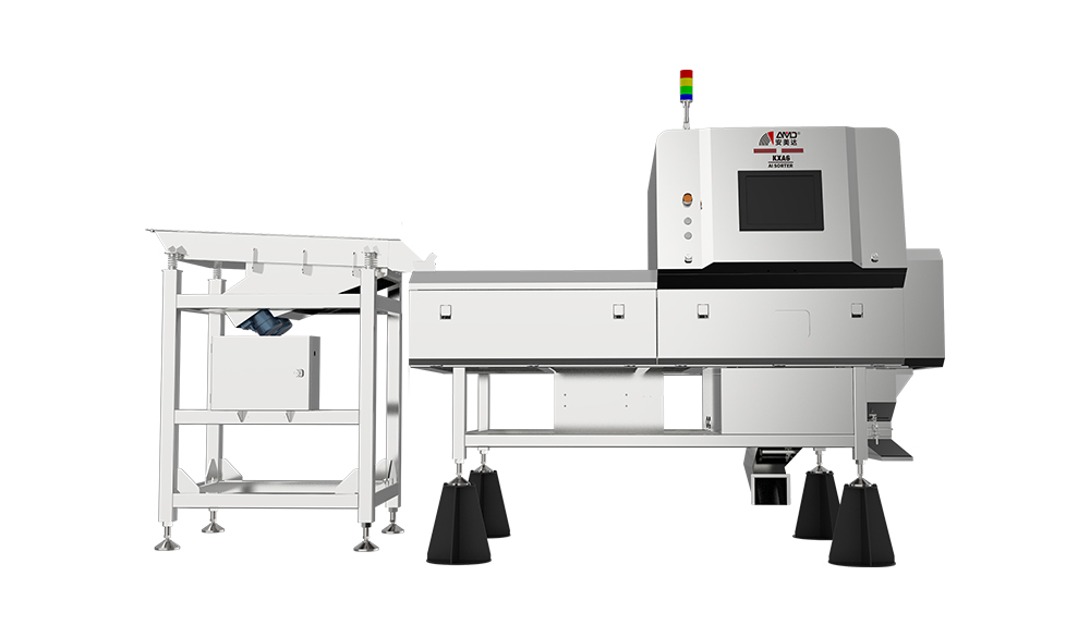
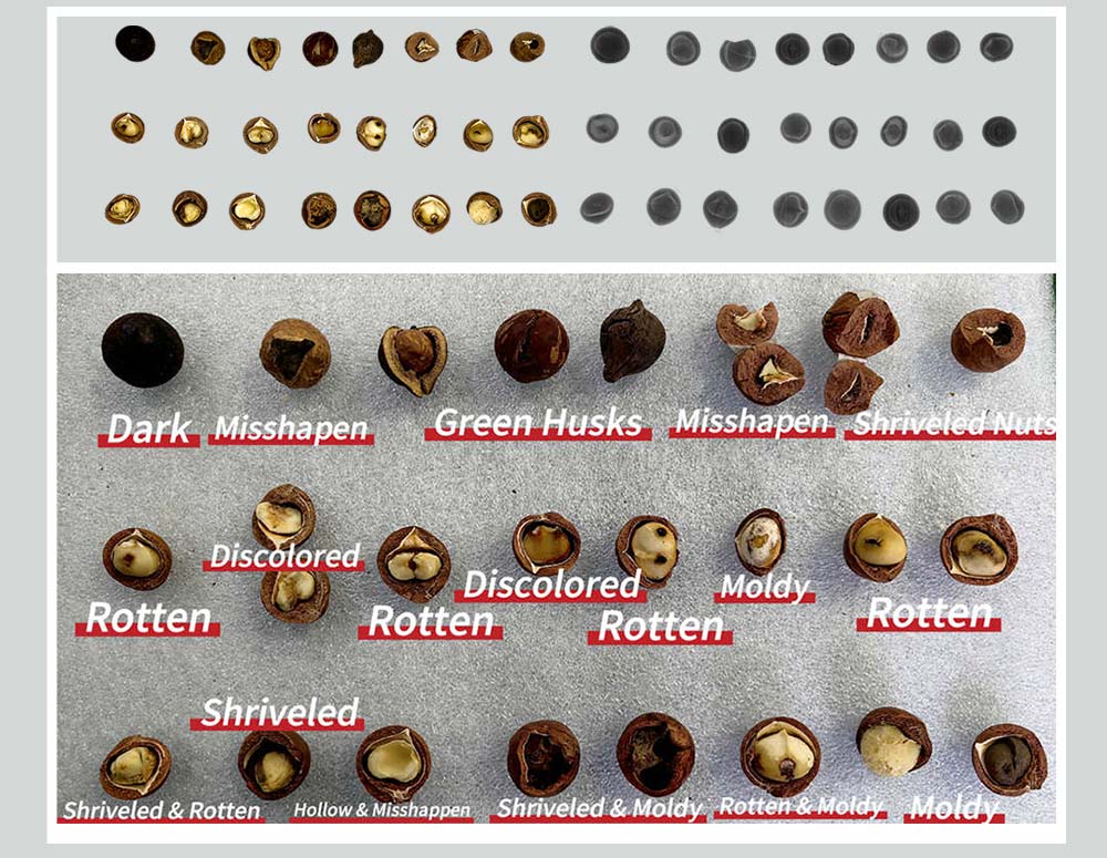
Internal Sorting The AMD® KXA6 Series X-ray inspection system can effectively remove the typical internal defects of macadamia nut-in-shell, such as empty, shriveled, discolored, cracked shell, rotten, insect-damaged nuts caused by stink bugs. Tailored algorithm for macadamia nuts, featuring large yield, high precision, low carry-out, low radiation value.
AMD® KXA6 Series X-ray Inspection System for Inshell Macadamia Nuts
Macadamia Nut Kernel Sorting
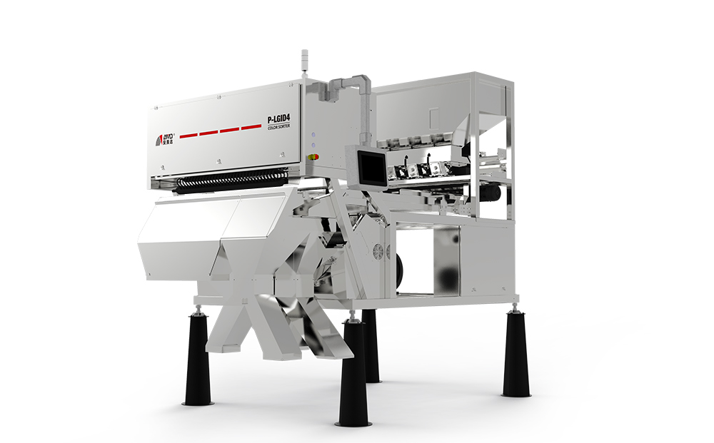
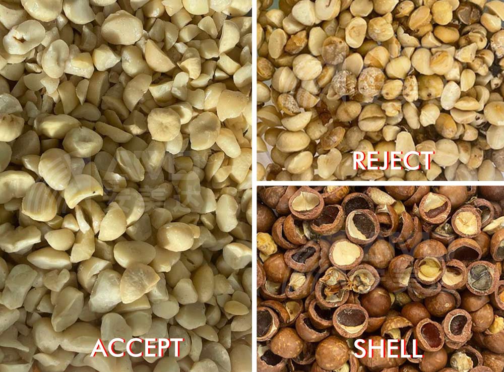
Based on AI deep learning, visible light and infrared sorting technology, AMD® P-LGID series sorting equipment can achieve kernel-shell separation while accurately identifying and separating different colours, and rejecting defective products such as insect damage, shrivelled, mouldy and dried.
AMD® P-LGID4 AI Sorting Machine for Macadamia Nut Kernel
Safeguarding food safety in nut processing. Boost efficiency, reduce waste, and minimize labor reliance. AMD® COLOR SORTER take macadamia nuts grading to new levels.
Get in touch with one of our sales manager today and get tailored macadamia nuts sorting machines & solution.
A solar panel production line is a manufacturing system specifically designed for the assembly and production of solar panels, which are devices that convert sunlight into electricity. It involves various processes and components to ensure the efficient and accurate manufacturing of solar panels.
Let's understand what a panel production line entails. It is a series of interconnected machines and equipment that work together to produce solar panels on a large scale. The production line typically consists of several key components:
Frame Cutting and Fabrication(Solar Cell Laser Cutting Machine): This step involves cutting and shaping the aluminum frames that provide structural support to the solar panels. It includes processes like cutting, milling, and drilling.
Glass Cleaning and Coating: The glass used in solar panels goes through a rigorous cleaning process to remove any impurities. Additionally, an anti-reflective coating may be applied to enhance the panel's light absorption.
Cell Stringing(Solar Cell Tabber Stringer): Solar cells, which are typically made of silicon, are interconnected to form a solar panel. This process involves precise placement and stringing of the cells using automated machinery.
Encapsulation(Solar Panel Laminator): The solar cells are encapsulated within a layer of protective material, such as ethylene-vinyl acetate (EVA), to ensure their durability and performance. This process often involves the use of lamination machines to create a secure bond.
Testing and Quality Control: After the panels are assembled, they undergo rigorous testing procedures to ensure their performance and efficiency meet industry standards. This includes electrical testing machine, visual inspection, and performance evaluation.
The components of a solar production line work collectively to streamline the manufacturing process and achieve high-quality solar panels. Each step is carefully executed to ensure accuracy, reliability, and efficiency.
The solar panel production line is a sophisticated assembly system that integrates various components and processes to produce solar panels at scale. From frame cutting and glass coating to cell stringing and encapsulation, each step plays a crucial role in creating reliable and efficient solar panels. Suposolar is a professional solar panel production line provider, get more information from us quickly.
In the rapidly evolving solar energy sector, Supo stands out with its innovative Turnkey Solar Panel Production Line, designed for manufacturers looking to enhance efficiency and output. Our comprehensive system simplifies the entire solar panel manufacturing process, from raw material handling to final assembly.
At the heart of our production line are advanced PV Module Machines that ensure high precision and performance. These machines optimize the workflow, minimizing waste and maximizing output. By integrating automation and cutting-edge technology, Suposolar enables manufacturers to scale operations quickly and adapt to dynamic market demands.
With our turnkey solution, everything—from equipment installation to staff training—is expertly managed by Supo, allowing businesses to focus on their core competencies. This streamlined approach not only reduces lead times but also ensures the production of high-quality solar panels that meet international standards.
As the global push for renewable energy continues, investing in Supo’s Solar Panel Production Line is essential for enhancing competitiveness and sustainability in the market. Embrace our technology and position your business for success in the solar industry.
Are you new to using power generators? Do you need a reliable and efficient generator for your offshore marine operations? Look no further than the LEHUI MTU 2300KVA Offshore Silent Canopy Emergency Marine Diesel Power Generator Set Electric Soundproof Genset 50HZ. In this guide, we will provide you with a step-by-step process to help you understand and utilize this powerful generator effectively.
Step 1: Familiarize Yourself with the Generator
Before using the LEHUI MTU 2300KVA Offshore Silent Canopy Emergency Marine Diesel Power Generator Set Electric Soundproof Genset 50HZ, it’s essential to familiarize yourself with its features and specifications. Take the time to read through the user manual provided by the manufacturer. Understanding the various components and their functions will ensure safe and efficient operation.
Step 2: Location and Installation
Choose an appropriate location for the generator installation. Look for a well-ventilated area with sufficient space for the generator and easy access for maintenance. Ensure that the installation meets all the safety regulations and requirements for marine vessels.
Step 3: Fuel and Cooling System
Check the fuel levels and ensure you have enough diesel to operate the generator. Properly connect the fuel lines and ensure there are no leaks. Additionally, inspect the cooling system to ensure it is functioning correctly.
Step 4: Start-Up Procedure
Follow these steps to start the generator:
Ensure all electrical loads are disconnected.
Turn the fuel supply to the generator on.
Prime the fuel system if necessary.
Set the control switch to the “Start” position.
Once the engine starts, release the start switch and monitor for any abnormalities.
Allow the generator to warm up before connecting any electrical loads.
Step 5: Operating the Generator
Once the generator is running, you can connect your electrical loads. Be sure to follow these guidelines:
Determine the power requirements of your electrical devices to avoid overloading the generator.
Use appropriate cables and connectors for a secure electrical connection.
Monitor the generator’s performance and operating parameters regularly.
Step 6: Maintenance and Safety
Regular maintenance is crucial to keep the LEHUI MTU 2300KVA Offshore Silent Canopy Emergency Marine Diesel Power Generator Set Electric Soundproof Genset 50HZ running smoothly. Follow the manufacturer’s maintenance schedule for specific guidelines. Additionally, prioritize safety by adhering to these precautions:
Keep the generator and its surrounding area clean and free from debris.
Regularly inspect fuel lines, electrical connections, and cooling systems for any signs of damage or deterioration.
Ensure proper ventilation to prevent the buildup of carbon monoxide.
Step 7: Shutdown Procedure
When you’re finished using the generator, follow this shutdown procedure:
Disconnect all electrical loads.
Allow the generator to run without a load for a few minutes to cool down.
Turn the control switch to the “Off” position.
Close the fuel supply valve.
Remember, always refer to the user manual provided by the manufacturer for specific instructions tailored to the LEHUI MTU 2300KVA Offshore Silent Canopy Emergency Marine Diesel Power Generator Set Electric Soundproof Genset 50HZ.
By following these steps and taking proper care of your generator, you can ensure its longevity and reliable performance in your offshore marine operations. Enjoy seamless power supply with the LEHUI MTU 2300KVA generator, and may your ventures be successful and powerful!
High quality defect data is crucial for training and optimizing AI visual inspection models on industrial production lines. To obtain rare and high-quality defect samples for product appearance defect detection, multiple layers of effort are required.
High yield rate and low defect rate, online collection of defect samples - time-consuming!
Product changeover, collecting a large number of defect samples in a short period of time - difficult!
Sample defects are complex and diverse, and collection is cumbersome - low efficiency!
Defect Generation
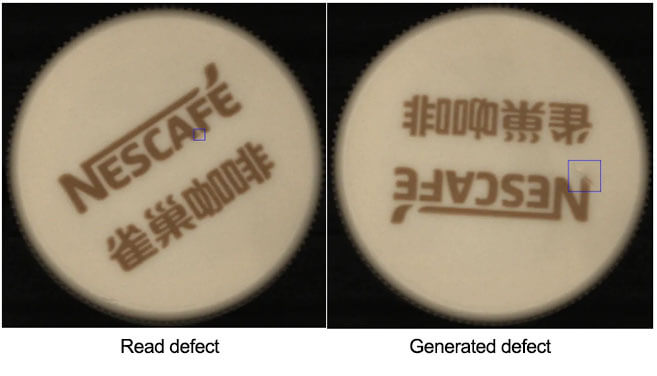
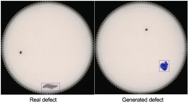
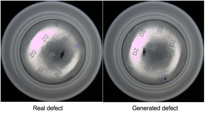
By using AI visual inspection and diffusion modeling techniques, various types, positions, and shapes of defect images can be simulated with only a small number of sample images through forward and backward diffusion algorithms. Simulated defect images are highly similar in appearance and features to actual defects, providing an effective solution to the problem of defect data scarcity.
Significant role of key nodes
Rapid model construction-Rare defect samples are few, and defects can be generated through "defect synthesis" to achieve rapid model construction in AI visual inspection.
Rapid deployment of models-Product changeover can utilize "defect synthesis" to quickly generate defects in related products for model training and rapid deployment.
Rapid improvement of the model-When there are missed defects on the production line, simulation defects can be generated through "defect synthesis" to quickly reduce production missed defects.
Intelligent, efficient, and easy to operate
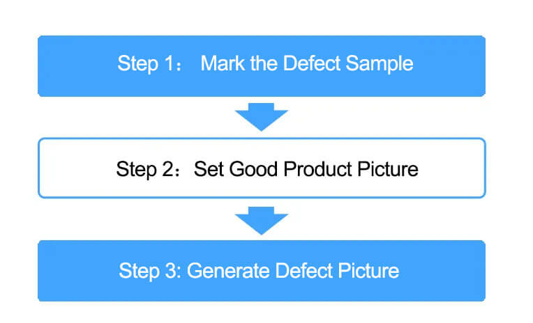
Defect synthesis "only requires three steps of marking defective samples, placing good products, and defect synthesis to generate a large number of high-quality defect maps, expand the training sample set, significantly shorten sample collection time, and achieve fast model training.
Strong performance and outstanding advantages
Strong applicability- Can be used for products and different defects in multiple industry sectors
Strong flexibility- Independently choose defect location, quantity, and type to meet personalized user needs
Easy to operate- Three step generation of defect maps, significantly saving time and cost
High Collaboration- The generated results come with annotation information, without the need for secondary annotation, and can be directly used for model training
Excellent effect- The generated defects are highly similar to real defects, greatly improving the training effectiveness of the model in AI visual inspection field.
Efficient generation of simulation defects
Bottle cap: logo print
Bottle cap: stains
Bottle cap: black spot
Generative AI plays an important role in the field of industrial vision. Through intelligent defect generation technology, KeyeTech Skill quickly generates a large number of defect images that are close to reality, solving the problem of scarce defect samples and time-consuming and laborious collection, greatly improving the training efficiency and generalization ability of AI visual inspection model!
Voice recognition, facial recognition unlocking... AI has penetrated every corner of our lives. In recent years, the application of AI is no longer limited to daily life; it has gradually begun to be implemented in the production systems of various industries, such as visual inspection, intelligent sorting, automatic packaging, and more. However, for industry applications, integrating AI into enterprise production models to improve production efficiency is not a smooth process and faces several challenges and difficulties.
In the industrial sector regarding visual inspection: Companies generate massive amounts of data during production processes, but how can they filter out valuable data? How can AI deep learning further enhance control and inspection accuracy? How to acquire and represent industry knowledge, and how to convert it into data that participates in AI calculations and creates value?
These challenges in applying AI to industries require continuous innovation and upgrades to AI platforms to address them.
1.Industry Applications: Huge AI Challenges
In the industrial field, especially in visual inspection, many AI applications face the contradiction of having limited sample data while the accuracy requirements remain high. Various sensors distributed across production equipment generate vast amounts of inspection data daily. However, the final quality of the product is jointly influenced by thousands of parameters such as process parameters, material properties, and production equipment—only a small proportion of the inspection data samples is directly meaningful for quality prediction analysis.
Furthermore, most companies are still relying on manual inspection, with widespread concerns that AI devices may not be as flexible as human inspection.
In the face of these challenges for industry applications, there is a need for a comprehensive and efficient AI machine that meets the demands of various industries for limited samples and high flexibility.
2.KeyeTech: Leading Capability in Industry AI Implementation
KeyeTech has developed AI image visual inspection equipment through years of continuous innovation and upgrades, enabling machines to possess collaborative and cognitive abilities similar to those of humans. Its AI platform can simulate massive data with a small number of samples, labeling and analyzing samples to build inspection models. It is also equipped with advantages such as high efficiency, stability, and the ability to switch between multiple models, solving issues related to the accuracy, efficiency, safety, and costs associated with manual inspection.
01 Quality Guardian
In light of the limited sample data faced by enterprises, KeyeTech’s AI platform, based on deep learning, has data augmentation capabilities that allow a small number of samples to simulate massive data, thereby constructing its own AI database. When the equipment is in operation and detects a defective product, it quickly eliminates defect, ensuring that the products leaving the factory are defect-free.
02 Professional Image Inspector
Customized LED light sources and industrial cameras are equipped with an intelligent processing platform. When the products to be tested enter the inspection area, the industrial camera can capture multiple photos in about 0.1 seconds. Through AI algorithms, it compares against the sample database, simulating human thought processes to conduct quality inspections on product appearances. Issues such as black edge, material deficiency, and deformation of bottles are quickly recognized and eliminated.
03 Safety Guardian
Currently, KeyeTech's AI visual inspection machineis applied in industries such as packaging, food, 3C (computer, communication, consumer electronics), and medical fields. By leveraging AI for quality inspection and classification, it can reduce the number of inspection personnel by two-thirds.
Technological innovation is a core element in developing new quality productive forces. Continuously strengthening innovation in artificial intelligence technology is essential for achieving high-level technological self-reliance and self-improvement.
Labor materials with higher technological content provide a powerful source of motivation for producing new quality productive forces. KeyeTech is deeply engaged in the artificial intelligence sector, continuously exploring and researching algorithms and computing power. In 2023, KeyeTech successfully developed its own AI computing unit, significantly accelerating the progress of visual inspection. In 2024, KeyeTech also achieved significant breakthroughs in algorithm research...
"It" the Efficient Assistant for Annotation
In the era of big data, data is undoubtedly a valuable resource. However, efficiently and accurately annotating vast amounts of data has become a significant challenge. Traditional manual annotation methods are inefficient and prone to errors. The application of KeyeTech's automatic annotation function is like a timely rain, opening new doors for data annotation.
Automatic annotation is based on deep learning and natural language processing technologies, capable of automatically recognizing text and image data. With just a click of the mouse, it can accurately identify and annotate sample defects, greatly improving annotation efficiency and significantly enhancing annotation quality.
"It" the Data Screening Steward
Compared to traditional training methods, KeyeTech places greater emphasis on meticulous data screening and strict quality control. Only positive samples that meet the requirements are selected for training, avoiding interference from incorrect or unexpected data during model training, thereby improving the accuracy and reliability of the model.
The core of positive sample training lies in its ability to learn from good product samples, enabling the machine to accurately identify and output correct training results, significantly enhancing recognition capabilities and data output accuracy.
A New Pathway Toward the Intelligent Era
With continuous technological innovation and the expansion of application scenarios, artificial intelligence is demonstrating limitless potential. For intelligent enterprises, optimizing upgrades, reforming innovations, and self-research production are crucial for development and progress.
Looking to the future, artificial intelligence will widely empower more fields, injecting vitality into the intelligent era. KeyeTech will refine its "skill value," unlock its "future power," and continue to delve into artificial intelligence, embarking on a new pathway toward intelligence and opening a new chapter of wisdom!
Two important elements defining the quality of machining are accuracy and precision. While accuracy gauges how closely a result is to the desired aim, precision describes how regularly a machine may repeat the same result. These two ideas are essential in manufacturing sectors where even little mistakes can cause expensive issues.
This article will discuss the value of accuracy and precision in machining and how modern technology, such as CNC machines, improves both.
What is the Difference Between Precision and Accuracy?
Though they define various aspects of measurement, accuracy, and precision are basic ideas in machining.
· Precision: Precision in machinery is the ability of a machine to perform a certain operation repeatedly. Even if the result is inaccurate, a CNC machine is said to be precise when it consistently generates the same result. Precision is about lowering variation in ongoing work. A CNC machine is accurate but not precise, for instance, if it routinely cuts metal 0.2 millimeters off target.
· Accuracy: This word describes the degree of proximity of a process's outcomes to the intended measurement. A machine is accurate if its cut exactly fits the needed specification. Accuracy by itself, though, is insufficient. Even an accurate machine might not run consistently without precision.
Consider a dartboard to help you understand this. Precision is when all the darts land in the same location, notwithstanding their distance from the bullseye. Though it's just one throw, accuracy is when the dart lands on the bullseye.
Excellent accuracy and precision combined with a CNC machine will help to lower material waste, increase efficiency, and satisfy the most exacting standards. That is vital in aerospace, automotive, and electronics sectors where every component must satisfy exact criteria. It Equipped with both features, a machine guarantees consistent, high-performance output.
Why Does Machining Precision Matter?
Machining requires precision for various reasons. Repeatability is among the main advantages of accuracy. In sectors like automotive or aerospace, each item must be the same even though parts are manufactured in great numbers. CNC machines guarantee that independent of production volume, every single component satisfies the same criteria thanks to their great precision.
These are the main causes of the great importance of accuracy:
· Consistency in Mass Production: A small variation can cause quality control problems throughout thousands of parts. For instance, a part may not operate as intended when assembled if it is routinely cut somewhat too small. Precision guarantees that every component is produced according to the same criteria, solving this issue.
· Reduced Material Waste: Precision machines effectively use materials, reducing waste. Any machining process flaw, no matter how little, can cause material to be modified or discarded. Along with costing more, this wastes priceless resources.
· Higher Quality Products: High precision guarantees that parts are created exactly as needed in sectors where safety and dependability rule, including medical equipment or aerospace. A product failure arising from even small differences may have disastrous results.
· Less Need for Adjustments: Precision lessens the demand for rework or corrections. Precisely produced pieces fit together, saving the need for further adjustments following machining.
In What Ways Could Accuracy Affect Machined Part Quality?
Precision guarantees repeatability; accuracy guarantees that items satisfy the intended standards. Accuracy is crucial for manufacturing important components—such as those found in medical equipment, electronics, or heavy machinery.
For instance, every flaw in a component you are machining for a high-performance engine can cause mechanical breakdown. The engine components must mesh precisely. A small difference can lead to friction, heat, and wear, degrading engine performance and lifetime. Accurate machining guarantees that every component fits together as it should.
Key Effects of Machining Accuracy:
· Meeting Tight Tolerances: Certain sectors demand items produced under very limited tolerances. Reaching these criteria depends on accurate machines. No matter how exact, inaccurate equipment can fail to reach these important tolerances and produce defective items.
· Assembly and Functionality: Accurate machining of components will result in proper fit and desired functionality. Accuracy guarantees that the product will function as intended, whether you are building a basic assembly line or a sophisticated aeronautical component.
· Improving Reliability: In sectors including medical equipment, even the smallest mistake can make all the difference between life and death. Reliable and precise operation of parts is guaranteed by accurate machining.
Accuracy vs. Precision Examples
Evaluating the performance of manufacturing activities depends much on accuracy and precision, which are independent factors. While precision indicates the machine's capacity to perform the same operation regularly, accuracy in CNC machining gauges a part's relative proximity to its intended dimensions. In order to keep specified dimensions, most CNC machines depend on computer software. Still, the outcomes may differ:
· Precise and Accurate: A CNC machine constantly generates parts with minimum errors that match the design criteria. One gets accuracy as well as precision.
· Accurate but Not Precise: Though the machine generates pieces almost within the specified measurements, the outcomes vary. While some components stray, others satisfy the criteria.
· Precise but Not Accurate: Although the machine always generates parts with the same measurements, those measurements deviate from the desired specifications. Though wrong, the parts are similar.
· Neither Precise Nor Accurate: The machine generates inconsistent pieces; none satisfy the needed standards.
Differentiating between accuracy and precision and independently measuring them will help to guarantee a high-quality machining operation. Examples illustrating how these two factors influence part machining are below:
1. Precision and Accuracy in Gear Manufacturing: Precision and accuracy define a CNC machine that generates gears with the right size and form for seamless operation. The machine is accurate but not exact; if the gears vary in size, they still fit appropriately.
2. Medical Device Production Accuracy: Medical equipment has high criteria. Though accuracy may be insufficient if some pieces vary, machine-produced parts with exact implant specifications could be accurate.
Knowing these differences optimizes the machining process, guaranteeing accuracy and precision for dependable, high-performance products.
Could A Machine Be Precise But Not Accurate?
A machine can be precise but not accurate at the same time indeed. In machining, this is a vital difference.
Suppose you are making cylindrical pieces on a lathe. The machine is exact since it generates the same output every time if it constantly generates pieces that are 0.5 millimeters bigger than the target diameter. The parts are not the right size; hence, they are not accurate either. That emphasizes how to separate traits—accuracy and precision—that must be optimized and call for separate optimization.
A machine can produce consistent components even if it is not accurate if it is exact; those parts will not satisfy the required criteria nevertheless. That can be a challenge in sectors like aerospace or automotive, where the pieces must precisely fit one another.
Key Differences:
· Precision: Always leads to the same outcome, even if it's wrong.
· Accuracy: generates the right outcome despite an erratic process.
Should a machine prove accurate but not exact, calibration could be necessary to fix the inaccuracy. Recalibrating the equipment can change the process to become exact and accurate.
Why Would A Machine Be Precise But Not Accurate?
Wear and tear, poor calibration, or incorrect setup can cause machines to grow imprecise or inaccurate. Even the best devices could need recalibration over time to keep accuracy and precision. Therefore, regular maintenance and calibration are essential to guarantee that devices satisfy the required criteria.
Although CNC Yangsen's machines are made to keep accuracy and precision throughout time, regular calibration helps to guarantee long-term performance.
How Do Machining Tolerances Affect Precision and Accuracy?
In machining, tolerances are deviations allowed from a given dimension. Tolerances allow a margin for slight deviations since no machine can generate precisely to specification every time.
Most machining processes find that the cost of output increases with decreasing tolerance. Tolerances are intimately connected to both accuracy and precision. Precise and accurate machines can generate parts regularly falling inside the necessary tolerance range.
Types of Tolerances:
· Tight Tolerances: These are applied even when the tiniest departure from the designated measurement could lead to issues. For an aviation engine, for instance, parts might have to be machined within a tolerance of 0.01 millimeters since even the tiniest change might compromise performance.
· Loose Tolerances: Looser tolerances can be employed in some areas where accuracy is unnecessary. For non-critical parts that won't be under stress or wear, for instance, looser tolerances allow for small variations from the intended size or form.
Machines such as the very precise CNC verticle machine centers offered by CNC Yangsen are perfect for exact tolerances. They guarantee that every part satisfies the necessary criteria by operating within quite small margins of error.
How Can You Make Machining Both Precise And Accurate?
High-quality parts require the proper mix of accuracy and precision. A precise but not accurate machine will regularly generate parts that are off. On the other hand, if a machine is accurate but not exact, it will only seldom generate parts that satisfy the criteria.
· Invest in High-Quality Machinery: Not every machine is built equal. While certain devices can offer accuracy and precision, others may be made for only one. CNC Yangsen's high-end machines provide accuracy and precision, guaranteeing constant outcomes.
· Maintain Equipment: Regular maintenance is even required of the most sophisticated machinery. Keeping machines both accurate and exact depends on proper maintenance, part replacement, and recalibration.
· Calibration: Frequent calibration guarantees machines' correctness throughout. Even the greatest machines can wander from their intended specs without calibration, producing inaccurate products.
Complex Machining Requires Precision And Accuracy, Why?
Ensuring that items satisfy the required criteria in complicated machining projects requires accuracy and precision. Complex jobs often call for a machine capable of preserving accuracy and precision throughout the process, including several processes, tight tolerances, and using several materials.
For instance, think of the manufacturing of an aircraft multi-part assembly. The whole assembly may suffer if one component is inaccurately or precisely lacking. In these situations, even little variations from the planned design can cause performance problems, safety hazards, or failure of the ultimate result.
For complex machining jobs, machines such as the 5-axis CNC machining centers from CNC Yangsen are perfect since they provide both accuracy and precision even when working with challenging materials or intricate geometries.
Complex Machining Applications Of Accuracy And Precision:
· Aerospace Components: High-precision machining guarantees that, under the worst conditions, all parts fit together exactly.
· Medical Devices: Errors in medical equipment can endanger people. Precision machining ensures the intended functionality of devices.
High-precision tools for these jobs would be CNC machining centers from CNC Yangsen. Designed to satisfy the strict criteria of various sectors, they provide accuracy and precision for the most important jobs.
How Do Precision and Accuracy Impact Efficiency and Cost?
Machining processes' cost and efficiency directly rely on accuracy and precision. Precise and accurate machines lower rework, reduce waste and boost production speed. Over time, this translates into notable cost reductions.
Accurate and exact machining of parts reduces the necessity of remakes or corrections. Because every part is created to exact standards, accurate machines help cut the time spent on quality control inspections.
Benefits of High-Precision and Accurate Machines:
· Reduced Waste: Consistent machine performance reduces waste of materials.
· Lower Rework Costs: Less time and money spent fixing mistakes equals fewer mistakes overall.
· Increased Production Speed: Faster and more dependably produced parts by precision machines raise general efficiency.
By providing unsurpassed precision and accuracy, lowering waste, and enhancing production efficiency, machines such as high-precision CNC turning centres help firms save time and money.
How to Improve Machining Precision and Accuracy?
Minimizing waste and manufacturing high-quality products depend on improved machining precision and accuracy. These are several strategies to get better:
· Regular Calibration: Machines are periodically calibrated to guarantee their operation within the intended tolerances.
· Use High-Quality Tools: Purchasing sharp, long-lasting cutting tools guarantees constant results and improved accuracy.
· Maintain Optimal Speeds: Correct feed rates and spindle speeds running machines guarantee accurate and precise components.
· Perform Routine Maintenance: Frequent maintenance and cleaning of machines helps to prevent mechanical problems generating mistakes.
· Stable Environment: Temperature swings and vibrations can affect accuracy; a controlled atmosphere reduces these influences.
Machining accuracy and precision will be much improved by applying these techniques.
Conclusion:
Producing high-quality products that meet industrial machining standards depends on accuracy and precision. Accuracy ensures that each component is produced to the appropriate standard, while precision ensures repeatability. For industries that require exacting standards, advanced CNC machines offer an ideal combination of both, making them absolutely indispensable.
Manufacturers can increase general product quality, lower waste, and achieve higher efficiency by choosing the correct equipment. If you want to improve your machining techniques, consider selecting CNC machines that are accessible at CNC Yangsen.
The Art and Science of Casting: A Deep Dive into an Ancient Craft
Casting is one of the oldest manufacturing processes known to humanity, and it remains a cornerstone of modern industry. From ancient sculptures to contemporary machinery parts, casting has played a pivotal role in shaping the world around us. In this blog, we’ll explore the fascinating world of casting, its historical significance, modern applications, and the intricate science behind this timeless craft.
A Brief History of Casting
Casting dates back to ancient civilizations, where artisans used simple techniques to create objects from metals. The earliest evidence of casting can be traced to the Bronze Age (around 3300–1200 BC), where the lost-wax casting method was used to produce intricate jewelry and tools. The ancient Egyptians, Greeks, and Chinese all utilized casting techniques to create everything from statues to weaponry.
The lost-wax method, or cire-perdue, involves creating a model of the object in wax, encasing it in a mold, and then heating it until the wax melts away, leaving a cavity into which molten metal is poured. This method allowed for the production of detailed and complex shapes that were previously unimaginable.
At its core, casting involves three main steps: preparing the mold, melting the material, and pouring the molten metal into the mold. Here’s a closer look at each step:
1. Mold Preparation**: The first step in casting is creating a mold that defines the shape of the final product. Molds can be made from various materials, including sand, clay, or metal. For complex designs, multiple-part molds or patterns are used. In some cases, especially in modern casting, molds are created using advanced technologies like 3D printing.
2. Melting the Material**: The material to be cast, often metal, must be heated to its melting point. Different metals have different melting points; for instance, aluminum melts at around 660°C (1220°F), while steel melts at about 1370°C (2500°F). Furnaces or other heating equipment are used to achieve these high temperatures.
3. Pouring and Cooling**: Once the material is molten, it is poured into the prepared mold. The molten metal fills the cavity of the mold and takes on its shape as it cools and solidifies. The cooling process must be controlled carefully to avoid defects such as cracks or uneven solidification.
Types of Casting Techniques
There are several casting methods, each suited to different types of projects:
- Sand Casting**: This is one of the most common and versatile casting methods, ideal for producing large and complex parts. Sand casting involves creating a mold from a mixture of sand and binder, which is then used to form the shape of the final product.
- Die Casting**: Die casting is a high-precision method used for producing detailed and complex shapes, often for small to medium-sized parts. It involves injecting molten metal into a steel mold under high pressure.
- Investment Casting**: Also known as lost-wax casting, this method is used for creating intricate and high-quality parts. The process involves creating a wax model, which is then coated in a ceramic shell. Once the shell is hardened, the wax is melted out, and molten metal is poured into the cavity.
- Continuous Casting**: This technique is used for producing metal bars or billets that are continuously cast from molten metal. It’s commonly used in the steel industry for creating long, uniform sections.
Modern Applications and Innovations
Casting technology has come a long way since its ancient origins. Today, casting is used in a wide range of industries, including automotive, aerospace, construction, and art. Modern advancements in casting technology, such as computer-aided design (CAD) and 3D printing, have significantly expanded the possibilities for creating complex and precise parts.
- Automotive Industry**: In the automotive sector, casting is used to produce engine blocks, transmission cases, and other critical components. High-strength alloys and precision casting techniques ensure that these parts meet the demanding requirements of modern vehicles.
- Aerospace**: The aerospace industry relies on casting to create components that must withstand extreme conditions. Advanced casting methods, such as investment casting, are used to produce turbine blades and other high-performance parts.
- Art and Sculpture**: Casting remains a popular technique for creating sculptures and art pieces. Modern artists use both traditional and innovative casting methods to bring their visions to life, often experimenting with new materials and techniques.
Casting is a remarkable blend of art and science, a testament to human ingenuity and craftsmanship that has evolved over thousands of years. Whether it’s creating intricate jewelry or producing high-strength components for advanced machinery, casting continues to play a vital role in our world. As technology progresses, the possibilities for casting are expanding, promising even more innovations and applications in the future.
Understanding the principles and techniques of casting not only gives us insight into a crucial manufacturing process but also connects us to the rich history of human creativity and technological advancement.
In the rapidly advancing world of automation, there is one solution that stands out for its exceptional performance in sorting tasks within the baking industry – the Delta Pick and Place Robot Parallel Delta Robot Industrial. With its unique features and benefits, this cutting-edge technology is revolutionizing the way we approach robotic sorting and picking in the baking world.
Unmatched Precision and Speed
The Delta Pick and Place Robot is renowned for its unparalleled precision and lightning-fast speed. Equipped with advanced sensors and intelligent algorithms, it ensures accurate and efficient sorting of baked goods such as bread and cakes. Whether it’s arranging items on a conveyor belt or transferring them from one location to another, this robot excels in every task with remarkable precision and speed.
Flexible and Versatile
With its parallel delta robot design, this innovative machine offers exceptional flexibility and versatility in handling various shapes, sizes, and weights of bakery products. From delicate pastries to sturdy loaves of bread, the Delta Pick and Place Robot adapts effortlessly to different objects, making it perfect for diverse sorting requirements in the baking industry. Its versatile grippers are designed to handle items gently, ensuring minimal damage or deformity during the picking and placing process.
Improved Efficiency and Productivity
Time is of the essence in the baking industry, and the Delta Pick and Place Robot understands this well. By automating the sorting and picking process, it eliminates the need for manual labor, thereby increasing overall efficiency and productivity. With its rapid cycle times and continuous operation, this robot can significantly reduce production times, allowing bakeries to meet higher demands without compromising on quality.
Enhanced Safety Measures
Safety is a top priority in any industrial setting, and the Delta Pick and Place Robot doesn’t disappoint. Equipped with advanced safety features, including collision detection and emergency stop capabilities, this robot ensures a secure working environment for both operators and other machinery. With these measures in place, potential accidents are minimized, providing peace of mind and boosting workplace safety standards.
Cost-Effective Solution
Implementing the Delta Pick and Place Robot brings numerous cost-saving benefits for bakery owners. By streamlining the sorting and picking processes, it reduces labor costs and minimizes errors that can occur with manual handling. Additionally, its energy-efficient design contributes to lower operating expenses, making it an economical choice for businesses looking to optimize their production lines.
Conclusion
The Delta Pick and Place Robot Parallel Delta Robot Industrial is undeniably a game-changer within the realm of robotic sorting and picking in the baking industry. Its unmatched precision, flexibility, and versatility make it the ideal solution for achieving efficient and accurate sorting of bread and cakes. With improved productivity, enhanced safety, and cost-effective operations, this innovative technology is revolutionizing the way we approach bakery automation. Embrace the future of robotic sorting and picking with the Delta Pick and Place Robot!