Precision vs Accuracy How Are They Important in Machining?

Two important elements defining the quality of machining are accuracy and precision. While accuracy gauges how closely a result is to the desired aim, precision describes how regularly a machine may repeat the same result. These two ideas are essential in manufacturing sectors where even little mistakes can cause expensive issues.

This article will discuss the value of accuracy and precision in machining and how modern technology, such as CNC machines, improves both.


What is the Difference Between Precision and Accuracy?

Though they define various aspects of measurement, accuracy, and precision are basic ideas in machining.

· Precision: Precision in machinery is the ability of a machine to perform a certain operation repeatedly. Even if the result is inaccurate, a CNC machine is said to be precise when it consistently generates the same result. Precision is about lowering variation in ongoing work. A CNC machine is accurate but not precise, for instance, if it routinely cuts metal 0.2 millimeters off target.

· Accuracy: This word describes the degree of proximity of a process's outcomes to the intended measurement. A machine is accurate if its cut exactly fits the needed specification. Accuracy by itself, though, is insufficient. Even an accurate machine might not run consistently without precision.

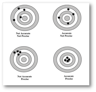
Consider a dartboard to help you understand this. Precision is when all the darts land in the same location, notwithstanding their distance from the bullseye. Though it's just one throw, accuracy is when the dart lands on the bullseye.

Excellent accuracy and precision combined with a CNC machine will help to lower material waste, increase efficiency, and satisfy the most exacting standards. That is vital in aerospace, automotive, and electronics sectors where every component must satisfy exact criteria. It Equipped with both features, a machine guarantees consistent, high-performance output.

Why Does Machining Precision Matter?

Machining requires precision for various reasons. Repeatability is among the main advantages of accuracy. In sectors like automotive or aerospace, each item must be the same even though parts are manufactured in great numbers. CNC machines guarantee that independent of production volume, every single component satisfies the same criteria thanks to their great precision.

These are the main causes of the great importance of accuracy:

· Consistency in Mass Production: A small variation can cause quality control problems throughout thousands of parts. For instance, a part may not operate as intended when assembled if it is routinely cut somewhat too small. Precision guarantees that every component is produced according to the same criteria, solving this issue.

· Reduced Material Waste: Precision machines effectively use materials, reducing waste. Any machining process flaw, no matter how little, can cause material to be modified or discarded. Along with costing more, this wastes priceless resources.

· Higher Quality Products: High precision guarantees that parts are created exactly as needed in sectors where safety and dependability rule, including medical equipment or aerospace. A product failure arising from even small differences may have disastrous results.

· Less Need for Adjustments: Precision lessens the demand for rework or corrections. Precisely produced pieces fit together, saving the need for further adjustments following machining.


In What Ways Could Accuracy Affect Machined Part Quality?

Precision guarantees repeatability; accuracy guarantees that items satisfy the intended standards. Accuracy is crucial for manufacturing important components—such as those found in medical equipment, electronics, or heavy machinery.

For instance, every flaw in a component you are machining for a high-performance engine can cause mechanical breakdown. The engine components must mesh precisely. A small difference can lead to friction, heat, and wear, degrading engine performance and lifetime. Accurate machining guarantees that every component fits together as it should.

Key Effects of Machining Accuracy:

· Meeting Tight Tolerances: Certain sectors demand items produced under very limited tolerances. Reaching these criteria depends on accurate machines. No matter how exact, inaccurate equipment can fail to reach these important tolerances and produce defective items.

· Assembly and Functionality: Accurate machining of components will result in proper fit and desired functionality. Accuracy guarantees that the product will function as intended, whether you are building a basic assembly line or a sophisticated aeronautical component.

· Improving Reliability: In sectors including medical equipment, even the smallest mistake can make all the difference between life and death. Reliable and precise operation of parts is guaranteed by accurate machining.


Accuracy vs. Precision Examples

Evaluating the performance of manufacturing activities depends much on accuracy and precision, which are independent factors. While precision indicates the machine's capacity to perform the same operation regularly, accuracy in CNC machining gauges a part's relative proximity to its intended dimensions. In order to keep specified dimensions, most CNC machines depend on computer software. Still, the outcomes may differ:

· Precise and Accurate: A CNC machine constantly generates parts with minimum errors that match the design criteria. One gets accuracy as well as precision.

· Accurate but Not Precise: Though the machine generates pieces almost within the specified measurements, the outcomes vary. While some components stray, others satisfy the criteria.

· Precise but Not Accurate: Although the machine always generates parts with the same measurements, those measurements deviate from the desired specifications. Though wrong, the parts are similar.

· Neither Precise Nor Accurate: The machine generates inconsistent pieces; none satisfy the needed standards.

Differentiating between accuracy and precision and independently measuring them will help to guarantee a high-quality machining operation. Examples illustrating how these two factors influence part machining are below:

1. Precision and Accuracy in Gear Manufacturing: Precision and accuracy define a CNC machine that generates gears with the right size and form for seamless operation. The machine is accurate but not exact; if the gears vary in size, they still fit appropriately.

2. Medical Device Production Accuracy: Medical equipment has high criteria. Though accuracy may be insufficient if some pieces vary, machine-produced parts with exact implant specifications could be accurate.

Knowing these differences optimizes the machining process, guaranteeing accuracy and precision for dependable, high-performance products.
Could A Machine Be Precise But Not Accurate?

A machine can be precise but not accurate at the same time indeed. In machining, this is a vital difference.

Suppose you are making cylindrical pieces on a lathe. The machine is exact since it generates the same output every time if it constantly generates pieces that are 0.5 millimeters bigger than the target diameter. The parts are not the right size; hence, they are not accurate either. That emphasizes how to separate traits—accuracy and precision—that must be optimized and call for separate optimization.

A machine can produce consistent components even if it is not accurate if it is exact; those parts will not satisfy the required criteria nevertheless. That can be a challenge in sectors like aerospace or automotive, where the pieces must precisely fit one another.

Key Differences:

· Precision: Always leads to the same outcome, even if it's wrong.

· Accuracy: generates the right outcome despite an erratic process.

Should a machine prove accurate but not exact, calibration could be necessary to fix the inaccuracy. Recalibrating the equipment can change the process to become exact and accurate.

Why Would A Machine Be Precise But Not Accurate?

Wear and tear, poor calibration, or incorrect setup can cause machines to grow imprecise or inaccurate. Even the best devices could need recalibration over time to keep accuracy and precision. Therefore, regular maintenance and calibration are essential to guarantee that devices satisfy the required criteria.

Although CNC Yangsen's machines are made to keep accuracy and precision throughout time, regular calibration helps to guarantee long-term performance.


How Do Machining Tolerances Affect Precision and Accuracy?

In machining, tolerances are deviations allowed from a given dimension. Tolerances allow a margin for slight deviations since no machine can generate precisely to specification every time.

Most machining processes find that the cost of output increases with decreasing tolerance. Tolerances are intimately connected to both accuracy and precision. Precise and accurate machines can generate parts regularly falling inside the necessary tolerance range.

Types of Tolerances:

· Tight Tolerances: These are applied even when the tiniest departure from the designated measurement could lead to issues. For an aviation engine, for instance, parts might have to be machined within a tolerance of 0.01 millimeters since even the tiniest change might compromise performance.

· Loose Tolerances: Looser tolerances can be employed in some areas where accuracy is unnecessary. For non-critical parts that won't be under stress or wear, for instance, looser tolerances allow for small variations from the intended size or form.

Machines such as the very precise CNC verticle machine centers offered by CNC Yangsen are perfect for exact tolerances. They guarantee that every part satisfies the necessary criteria by operating within quite small margins of error.


How Can You Make Machining Both Precise And Accurate?

High-quality parts require the proper mix of accuracy and precision. A precise but not accurate machine will regularly generate parts that are off. On the other hand, if a machine is accurate but not exact, it will only seldom generate parts that satisfy the criteria.

· Invest in High-Quality Machinery: Not every machine is built equal. While certain devices can offer accuracy and precision, others may be made for only one. CNC Yangsen's high-end machines provide accuracy and precision, guaranteeing constant outcomes.

· Maintain Equipment: Regular maintenance is even required of the most sophisticated machinery. Keeping machines both accurate and exact depends on proper maintenance, part replacement, and recalibration.

· Calibration: Frequent calibration guarantees machines' correctness throughout. Even the greatest machines can wander from their intended specs without calibration, producing inaccurate products.


Complex Machining Requires Precision And Accuracy, Why?

Ensuring that items satisfy the required criteria in complicated machining projects requires accuracy and precision. Complex jobs often call for a machine capable of preserving accuracy and precision throughout the process, including several processes, tight tolerances, and using several materials.

For instance, think of the manufacturing of an aircraft multi-part assembly. The whole assembly may suffer if one component is inaccurately or precisely lacking. In these situations, even little variations from the planned design can cause performance problems, safety hazards, or failure of the ultimate result.

For complex machining jobs, machines such as the 5-axis CNC machining centers from CNC Yangsen are perfect since they provide both accuracy and precision even when working with challenging materials or intricate geometries.

Complex Machining Applications Of Accuracy And Precision:

· Aerospace Components: High-precision machining guarantees that, under the worst conditions, all parts fit together exactly.

· Medical Devices: Errors in medical equipment can endanger people. Precision machining ensures the intended functionality of devices.

High-precision tools for these jobs would be CNC machining centers from CNC Yangsen. Designed to satisfy the strict criteria of various sectors, they provide accuracy and precision for the most important jobs.


How Do Precision and Accuracy Impact Efficiency and Cost?

Machining processes' cost and efficiency directly rely on accuracy and precision. Precise and accurate machines lower rework, reduce waste and boost production speed. Over time, this translates into notable cost reductions.

Accurate and exact machining of parts reduces the necessity of remakes or corrections. Because every part is created to exact standards, accurate machines help cut the time spent on quality control inspections.

Benefits of High-Precision and Accurate Machines:

· Reduced Waste: Consistent machine performance reduces waste of materials.

· Lower Rework Costs: Less time and money spent fixing mistakes equals fewer mistakes overall.

· Increased Production Speed: Faster and more dependably produced parts by precision machines raise general efficiency.

By providing unsurpassed precision and accuracy, lowering waste, and enhancing production efficiency, machines such as high-precision CNC turning centres help firms save time and money.


How to Improve Machining Precision and Accuracy?

Minimizing waste and manufacturing high-quality products depend on improved machining precision and accuracy. These are several strategies to get better:

· Regular Calibration: Machines are periodically calibrated to guarantee their operation within the intended tolerances.

· Use High-Quality Tools: Purchasing sharp, long-lasting cutting tools guarantees constant results and improved accuracy.

· Minimize Tool Wear: Changing tired tools immediately helps avoid machining process mistakes.

· Maintain Optimal Speeds: Correct feed rates and spindle speeds running machines guarantee accurate and precise components.

· Perform Routine Maintenance: Frequent maintenance and cleaning of machines helps to prevent mechanical problems generating mistakes.

· Stable Environment: Temperature swings and vibrations can affect accuracy; a controlled atmosphere reduces these influences.

Machining accuracy and precision will be much improved by applying these techniques.


Conclusion:

Producing high-quality products that meet industrial machining standards depends on accuracy and precision. Accuracy ensures that each component is produced to the appropriate standard, while precision ensures repeatability. For industries that require exacting standards, advanced CNC machines offer an ideal combination of both, making them absolutely indispensable.

Manufacturers can increase general product quality, lower waste, and achieve higher efficiency by choosing the correct equipment. If you want to improve your machining techniques, consider selecting CNC machines that are accessible at CNC Yangsen.
About casting-quanzhou jingda machinery co.,ltd gravity casting machine core shooter machine

The Art and Science of Casting: A Deep Dive into an Ancient Craft


Casting is one of the oldest manufacturing processes known to humanity, and it remains a cornerstone of modern industry. From ancient sculptures to contemporary machinery parts, casting has played a pivotal role in shaping the world around us. In this blog, we’ll explore the fascinating world of casting, its historical significance, modern applications, and the intricate science behind this timeless craft.


A Brief History of Casting


Casting dates back to ancient civilizations, where artisans used simple techniques to create objects from metals. The earliest evidence of casting can be traced to the Bronze Age (around 3300–1200 BC), where the lost-wax casting method was used to produce intricate jewelry and tools. The ancient Egyptians, Greeks, and Chinese all utilized casting techniques to create everything from statues to weaponry.


The lost-wax method, or cire-perdue, involves creating a model of the object in wax, encasing it in a mold, and then heating it until the wax melts away, leaving a cavity into which molten metal is poured. This method allowed for the production of detailed and complex shapes that were previously unimaginable.


 How Gravity Casting Machine Works: The Basic Process


At its core, casting involves three main steps: preparing the mold, melting the material, and pouring the molten metal into the mold. Here’s a closer look at each step:


1. Mold Preparation**: The first step in casting is creating a mold that defines the shape of the final product. Molds can be made from various materials, including sand, clay, or metal. For complex designs, multiple-part molds or patterns are used. In some cases, especially in modern casting, molds are created using advanced technologies like 3D printing.


2. Melting the Material**: The material to be cast, often metal, must be heated to its melting point. Different metals have different melting points; for instance, aluminum melts at around 660°C (1220°F), while steel melts at about 1370°C (2500°F). Furnaces or other heating equipment are used to achieve these high temperatures.


3. Pouring and Cooling**: Once the material is molten, it is poured into the prepared mold. The molten metal fills the cavity of the mold and takes on its shape as it cools and solidifies. The cooling process must be controlled carefully to avoid defects such as cracks or uneven solidification.


Types of Casting Techniques


There are several casting methods, each suited to different types of projects:


- Sand Casting**: This is one of the most common and versatile casting methods, ideal for producing large and complex parts. Sand casting involves creating a mold from a mixture of sand and binder, which is then used to form the shape of the final product.


- Die Casting**: Die casting is a high-precision method used for producing detailed and complex shapes, often for small to medium-sized parts. It involves injecting molten metal into a steel mold under high pressure.


- Investment Casting**: Also known as lost-wax casting, this method is used for creating intricate and high-quality parts. The process involves creating a wax model, which is then coated in a ceramic shell. Once the shell is hardened, the wax is melted out, and molten metal is poured into the cavity.


- Continuous Casting**: This technique is used for producing metal bars or billets that are continuously cast from molten metal. It’s commonly used in the steel industry for creating long, uniform sections.


 Modern Applications and Innovations


Casting technology has come a long way since its ancient origins. Today, casting is used in a wide range of industries, including automotive, aerospace, construction, and art. Modern advancements in casting technology, such as computer-aided design (CAD) and 3D printing, have significantly expanded the possibilities for creating complex and precise parts.


- Automotive Industry**: In the automotive sector, casting is used to produce engine blocks, transmission cases, and other critical components. High-strength alloys and precision casting techniques ensure that these parts meet the demanding requirements of modern vehicles.


- Aerospace**: The aerospace industry relies on casting to create components that must withstand extreme conditions. Advanced casting methods, such as investment casting, are used to produce turbine blades and other high-performance parts.


- Art and Sculpture**: Casting remains a popular technique for creating sculptures and art pieces. Modern artists use both traditional and innovative casting methods to bring their visions to life, often experimenting with new materials and techniques.


Casting is a remarkable blend of art and science, a testament to human ingenuity and craftsmanship that has evolved over thousands of years. Whether it’s creating intricate jewelry or producing high-strength components for advanced machinery, casting continues to play a vital role in our world. As technology progresses, the possibilities for casting are expanding, promising even more innovations and applications in the future. 


Understanding the principles and techniques of casting not only gives us insight into a crucial manufacturing process but also connects us to the rich history of human creativity and technological advancement.

Delta Pick and Place Robot Revolutionizing Robotic Sorting and Baking Picking And Placing

In the rapidly advancing world of automation, there is one solution that stands out for its exceptional performance in sorting tasks within the baking industry – the Delta Pick and Place Robot Parallel Delta Robot Industrial. With its unique features and benefits, this cutting-edge technology is revolutionizing the way we approach robotic sorting and picking in the baking world.

Unmatched Precision and Speed

The Delta Pick and Place Robot is renowned for its unparalleled precision and lightning-fast speed. Equipped with advanced sensors and intelligent algorithms, it ensures accurate and efficient sorting of baked goods such as bread and cakes. Whether it’s arranging items on a conveyor belt or transferring them from one location to another, this robot excels in every task with remarkable precision and speed.

Flexible and Versatile

With its parallel delta robot design, this innovative machine offers exceptional flexibility and versatility in handling various shapes, sizes, and weights of bakery products. From delicate pastries to sturdy loaves of bread, the Delta Pick and Place Robot adapts effortlessly to different objects, making it perfect for diverse sorting requirements in the baking industry. Its versatile grippers are designed to handle items gently, ensuring minimal damage or deformity during the picking and placing process.

Improved Efficiency and Productivity

Time is of the essence in the baking industry, and the Delta Pick and Place Robot understands this well. By automating the sorting and picking process, it eliminates the need for manual labor, thereby increasing overall efficiency and productivity. With its rapid cycle times and continuous operation, this robot can significantly reduce production times, allowing bakeries to meet higher demands without compromising on quality.

Enhanced Safety Measures

Safety is a top priority in any industrial setting, and the Delta Pick and Place Robot doesn’t disappoint. Equipped with advanced safety features, including collision detection and emergency stop capabilities, this robot ensures a secure working environment for both operators and other machinery. With these measures in place, potential accidents are minimized, providing peace of mind and boosting workplace safety standards.

Cost-Effective Solution

Implementing the Delta Pick and Place Robot brings numerous cost-saving benefits for bakery owners. By streamlining the sorting and picking processes, it reduces labor costs and minimizes errors that can occur with manual handling. Additionally, its energy-efficient design contributes to lower operating expenses, making it an economical choice for businesses looking to optimize their production lines.

Conclusion

The Delta Pick and Place Robot Parallel Delta Robot Industrial is undeniably a game-changer within the realm of robotic sorting and picking in the baking industry. Its unmatched precision, flexibility, and versatility make it the ideal solution for achieving efficient and accurate sorting of bread and cakes. With improved productivity, enhanced safety, and cost-effective operations, this innovative technology is revolutionizing the way we approach bakery automation. Embrace the future of robotic sorting and picking with the Delta Pick and Place Robot!

A Step-By-Step Guide to Using the LEHUI Cummins 63KVA Rental Diesel Generator Set 60HZ

Are you a beginner who needs a reliable power source? Look no further! In this guide, we’ll walk you through the process of using the LEHUI Cummins 63KVA Rental Diesel Generator Set 60HZ. Whether you’re powering your events, construction sites, or emergency backup, this generator set is your perfect companion. Let’s get started!

Step 1: Familiarize Yourself with the Generator

Before using any equipment, it’s crucial to understand its components. The LEHUI Cummins 63KVA Rental Diesel Generator Set 60HZ consists of the following parts:

  • Engine: This is the heart of the generator, responsible for generating power.

  • Alternator: Converts the mechanical energy produced by the engine into electrical energy.

  • Control Panel: Allows you to start, stop, and monitor the generator’s performance.

  • Fuel Tank: Stores diesel fuel to power the generator.

  • Cooling System: Maintains optimal operating temperature for the generator.

Step 2: Perform a Safety Check

Safety should always be your top priority. Follow these steps to ensure a safe environment:

  1. Find a well-ventilated area and ensure the generator is on a level surface.

  2. Check the fuel level to ensure there is enough diesel fuel for your needs.

  3. Inspect the generator for any visible damage or leaks.

  4. Make sure all cables and connections are secure and in good condition.

Step 3: Start the Generator

Now that you’ve completed the safety check, you’re ready to start the generator:

  1. Locate the control panel and turn the key to the “ON” position.

  2. Check the control panel for any error codes or warning lights.

  3. Press the “Start” button and allow the generator to warm up for a few minutes.

Step 4: Connect Your Devices

With the generator up and running, it’s time to connect your devices to the power supply:

  1. Identify the outlets on the control panel suitable for your devices.

  2. Use appropriate cables and connectors to connect your devices to the generator.

  3. Make sure the total power consumption of your devices is within the generator’s capacity.

Step 5: Monitor and Maintain

While the generator is in use, keep an eye on its performance and perform regular maintenance:

  1. Monitor the control panel for any irregularities or error codes.

  2. Check the fuel levels periodically and refill when necessary.

  3. Regularly inspect cables and connections for any signs of wear.

  4. Follow the manufacturer’s guidelines for routine maintenance.

Step 6: Shutdown

When you’re finished using the generator, follow the proper shutdown procedure:

  1. Disconnect all devices from the generator.

  2. Turn the key to the “OFF” position on the control panel.

  3. Allow the generator to cool down before storing it.

Congratulations! You have successfully learned how to use the LEHUI Cummins 63KVA Rental Diesel Generator Set 60HZ. Remember to prioritize safety and perform regular maintenance to keep the generator in top condition.

Disclaimer: This guide provides general instructions. Always refer to the manufacturer’s manual for specific guidelines and safety procedures.

Factory Direct Supply Tin Can Fish Tuna/Sardine Seafood Packaging Production Line - What Makes it Exceptional?

In today’s fast-paced world, where convenience and quality are paramount, the production of canned seafood plays a significant role in meeting the demands of consumers. Two popular choices in the market are tin can fish tuna and sardine, both enjoyed for their versatility and nutritional benefits.

To ensure these seafood delicacies are packaged efficiently and adhere to strict quality standards, manufacturers depend on state-of-the-art production lines. In this article, we will explore the fascinating world of the Tin Can Fish Tuna and Sardine Seafood Packaging Production Line, and understand why factory direct supply is the pinnacle of excellence.

The Tin Can Fish Tuna Production Line

Creating that perfectly canned tuna begins with the intricate Tin Can Fish Tuna Production Line. This advanced assembly system boasts impressive efficiency and precision, guaranteeing every can is filled with premium chunks of tuna. From processing and filleting, to cooking and canning, the production line seamlessly moves through each stage, ensuring top-notch seafood quality.

The Tin Can Fish Tuna Production Line encompasses various essential components. Automated cutting machines accurately slice the tuna into consistent portions, while cleaning machines remove any impurities. Then, the specially designed cooking machinery masterfully cooks the tuna, intensifying its flavor and texture. Finally, the automated canning process ensures that each can is sealed tightly, securing freshness and taste.

The Sardine Seafood Packaging Production Line

Equally important in the seafood industry is the Sardine Seafood Packaging Production Line. This remarkable system handles the delicate sardines with precision, providing a seamless packaging process. From cleaning and canning to labelling and packaging, this line ensures sardines reach consumers in their prime state, ready to satisfy gourmet palates.

The Sardine Seafood Packaging Production Line boasts sophisticated machinery that guarantees optimal results. Elaborate cleaning mechanisms efficiently rid the sardines of scales and impurities, maintaining their pristine condition. The canning process flawlessly seals in the sardines, preserving their rich flavor and nutritional value. Finally, labels are expertly applied, providing crucial information to consumers.

Factory Direct Supply: The Epitome of Excellence

Factory direct supply is the epitome of excellence in the Tin Can Fish Tuna and Sardine Seafood Packaging Production Line. By eliminating intermediaries, manufacturers can ensure that every step of the process meets precise specifications. This streamlined approach allows for unparalleled quality control and customer satisfaction.

Direct supply also enables manufacturers to stay at the forefront of innovation. They can invest in cutting-edge technology, ensuring their production lines remain state-of-the-art. This commitment to advancement guarantees that every can of tin can fish tuna or sardines is packed using the most advanced techniques, resulting in superior quality and taste.

In conclusion, the Tin Can Fish Tuna and Sardine Seafood Packaging Production Line represent the pinnacle of excellence in the seafood industry. Combining superior machinery, intricate processes, and direct supply, manufacturers produce canned tuna and sardines that meet the highest standards. So, the next time you grab a can of these delectable seafood options, remember the remarkable journey it took from the production line to your plate.

Comparing and Contrasting Videojet V852-R and Videojet V572-R A Comprehensive Analysis

In today’s fast-paced manufacturing industry, efficiency and reliability are key factors to consider when it comes to industrial printing systems. Videojet, a renowned brand in the field, offers a wide range of products and services to meet the diverse needs of businesses. Two popular options, the Videojet V852-R and the Videojet V572-R, are often compared and contrasted for their capabilities and performance. In this article, we will explore the features of these two Videojet products, as well as other related offerings, such as the Videojet CIJ printer spares, Videojet 1000 Series parts, and ink chips for Videojet printers.

Videojet V852-R: Power and Precision Combined

The Videojet V852-R is a high-tech coding and marking solution designed to deliver exceptional print quality and reliability. This advanced system incorporates cutting-edge technology, enabling it to handle complex printing tasks with ease. The V852-R boasts a user-friendly interface, allowing operators to easily control and monitor the printing process. With its high-speed capabilities and impressive uptime, this printer ensures maximum productivity for businesses operating in demanding environments.

Videojet V572-R: Versatility and Performance at its Best

The Videojet V572-R is another popular choice in the Videojet product line. This printer offers exceptional versatility, making it suitable for various applications across different industries. Equipped with advanced features and a robust design, the V572-R provides outstanding performance, even in challenging conditions. Its intuitive interface allows operators to quickly set up and operate the printer with minimal training. The V572-R also offers cost-effective solutions, with efficient ink usage and low maintenance requirements.

Videojet CIJ Printer Spares: Ensuring Continuous Operations

To ensure the smooth functioning of their coding and marking systems, businesses often require spare parts for their Videojet CIJ printers. Videojet understands this need and offers a comprehensive range of CIJ printer spares. These spares are designed to fit seamlessly into the Videojet printers, allowing for quick and efficient replacements whenever necessary. With high-quality OEM parts available at hand, businesses can minimize downtime and keep their operations running smoothly.

Videojet 1000 Series Parts: Adaptable Solutions for Every Industry

The Videojet 1000 Series of printers provides reliable coding and marking solutions for various industries, from food and beverage to pharmaceuticals and automotive. To ensure the longevity of these printers, Videojet offers a range of parts specifically designed for the 1000 Series. These genuine Videojet parts are durable and compatible with the printers, ensuring consistent performance and enabling businesses to meet their coding and marking requirements effectively.

Ink Chips for Videojet Printers: Enhancing Efficiency and Cost Savings

Ink chips play a vital role in ensuring smooth ink flow and optimal performance of Videojet printers. Videojet offers ink chips specifically tailored for their printers, such as the V572-R. These ink chips are designed to provide accurate ink level readings, allowing businesses to avoid interruptions caused by running out of ink. By using genuine Videojet ink chips, businesses can optimize ink usage, minimize wastage, and ultimately reduce overall printing costs.

In conclusion, both the Videojet V852-R and V572-R offer exceptional features and performance, catering to the diverse needs of the manufacturing industry. Additionally, Videojet’s extensive range of CIJ printer spares, Videojet 1000 Series parts, and ink chips further enhance the efficiency and reliability of their printers. Whether businesses require high-speed printing, versatility, or cost-effectiveness, Videojet provides comprehensive solutions to meet their coding and marking requirements. With Videojet’s commitment to innovation and quality, businesses can rely on their products to streamline operations and achieve exceptional results.

Advantages of EPR Spectroscopy

EPR (Electron Paramagnetic Resonance) Spectroscopy, also known as Electron Spin Resonance (ESR) Spectroscopy, is a versatile analytical technique used to study materials containing unpaired electrons. Through careful manipulation of the electron spins EPR spectroscopy can provide valuable insights into molecular structure, dynamics, and electronic properties.

In this blog post, we will delve into the advantages of EPR spectroscopy and its wide range of applications.


Highly sensitive detection:

EPR spectroscopy is extremely sensitive and can detect and characterize paramagnetic species even at very low concentrations. It can identify and quantify trace amounts of free radicals, transition metal ions, and unstable molecular species. This sensitivity makes EPR spectroscopy an invaluable tool for the study of a variety of biological processes such as oxidative stress, enzyme reactions, and DNA damage, as well as for materials research in areas such as physics and materials science.


Structural Information:

EPR spectroscopy provides valuable information about the structure and environment of paramagnetic species. By measuring the g-factor (a dimensionless number representing the spin behavior of electrons) and hyperfine splitting (resulting from electron-nucleus interactions), researchers can infer the electronic structure, bond distances, coordination environments, and magnetic properties of the substance under study. This structural insight is essential for understanding chemical reaction mechanisms and for designing and optimizing catalysts and materials with specific properties.


Dynamic process studies:

EPR spectroscopy can study dynamic processes in a variety of systems. For example, it can probe the motion and dynamics of spin-labeled biomolecules and is used to study protein folding, membrane dynamics, and enzyme dynamics. By monitoring changes in the EPR signal over time, researchers can gain insight into reaction rates, conformational changes, and molecular interactions. The ability to study dynamic processes in real-time makes EPR an important tool in biochemistry and biophysics.


Non-destructive and versatile:

EPR spectroscopy is a non-destructive technique that allows researchers to study samples without altering their integrity or composition. This advantage is particularly important when studying fragile biological samples, where it is critical to maintain the integrity of the sample. In addition, EPR spectroscopy is versatile and applicable to many types of samples, including liquid, solid, gas and biological samples. This versatility allows researchers to address a wide range of scientific questions in different disciplines.


Complementary Techniques:

EPR spectroscopy is often used in conjunction with other analytical techniques such as NMR (Nuclear Magnetic Resonance), X-ray crystallography and mass spectrometry. These complementary techniques allow researchers to correlate structural, electronic, and magnetic information to gain a more complete understanding of chemical systems. By combining EPR spectroscopy with other methods, researchers can characterize complex materials and biomolecules in greater detail and with greater reliability.


EPR spectroscopy plays a vital role in modern scientific research, providing unique insights into the structure, dynamics, and properties of paramagnetic species. Its sensitivity, ability to provide structural information, and non-destructive nature make it an indispensable tool in a wide range of scientific disciplines. Through the continued advancement and application of EPR spectroscopy, we can deepen our understanding of the natural world and devise innovative solutions to complex challenges in fields as diverse as chemistry, biology, and materials science.


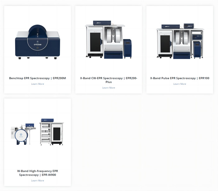
CIQTEK is a leading EPR spectrometer global manufacturer. Its EPR equipment offers high performance at a competitive price, making it an ideal choice for scientists.

Website: https://www.ciqtekglobal.com/


Here are some key advantages of CIQTEK's EPR spectrometers:


1. Affordable Solutions: CIQTEK aims to provide cost-effective EPR spectroscopy equipment without compromising quality. They offer different pricing options to suit various budgets, ensuring researchers get value for their investment.

2. Customizable Configurations: CIQTEK offers flexible EPR instrument setups, which can be tailored to meet specific experimental requirements. Researchers can customize features such as temperature control, multi-frequency capability, advanced spectroscopic techniques (ELDOR and HYSCORE), and compatibility with different sample types (liquids, solids, and biological materials).

3. User-Friendly Interface: CIQTEK's instruments are equipped with intuitive software interfaces, designed to be user-friendly for researchers of all experience levels.

4. Exceptional Customer Support: CIQTEK prioritizes customer satisfaction, providing excellent post-sales support. This includes comprehensive training resources, technical assistance, and access to customer stories and publications, showcasing their global EPR community.

CIQTEK's EPR spectrometers


Application Cases | Application of Field Emission SEM in Electrolytic Copper Foil

High-performance lithium copper foil is one of the key materials for lithium-ion batteries and is closely related to battery performance. With the increasing demand for higher capacity, higher density, and faster charging in electronic devices and new energy vehicles, the requirements for battery materials have also been raised. In order to achieve better battery performance, it is necessary to improve the overall technical indicators of lithium copper foil, including its surface quality, physical properties, stability, and uniformity.


Analysis of microstructure using scanning electron microscope-EBSD technique


In materials science, the composition and microstructure determine the mechanical properties. Scanning Electron Microscope (SEM) is a commonly used scientific instrument for the surface characterization of materials, allowing observation of the surface morphology of copper foil and the distribution of grains. In addition, Electron Backscatter Diffraction (EBSD) is a widely used characterization technique for analyzing the microstructure of metallic materials. By configuring an EBSD detector on a field-emission scanning electron microscope, researchers can establish the relationship between processing, microstructure, and mechanical properties.


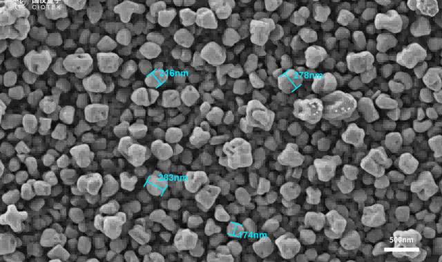
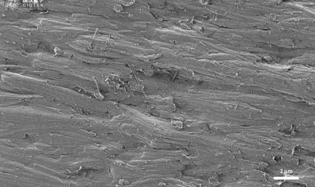
The figure below shows the surface morphology of electrolytic copper foil captured by the CIQTEK Field-emission SEM5000

 CIQTEK Copper Foil Smooth Surface

Copper Foil Smooth Surface/2kV/ETD

Copper Foil Matte Surface/2kV/ETD

When the sample surface is sufficiently flat, electron channel contrast imaging (ECCI) can be obtained using the SEM backscatter detector. The electron channeling effect refers to a significant reduction in the reflection of electrons from crystal lattice points when the incident electron beam satisfies the Bragg diffraction condition, allowing many electrons to penetrate the lattice and exhibit a "channeling" effect. Therefore, for polished flat polycrystalline materials, the intensity of backscatter electrons depends on the relative orientation between the incident electron beam and the crystal planes. Grains with larger misorientation will yield stronger backscattered electron signals and higher contrast, enabling the qualitative determination of grain orientation distribution through ECCI.


The advantage of ECCI lies in its ability to observe a larger area on the sample surface. Therefore, before EBSD acquisition, ECCI imaging can be used for rapid macroscopic characterization of the microstructure on the sample surface, including observation of grain size, crystallographic orientation, deformation zones, etc. Then, EBSD technology can be used to set the appropriate scanning area and step size for crystallographic orientation calibration in the regions of interest. The combination of EBSD and ECCI fully utilizes the advantages of crystallographic orientation imaging techniques in materials research.


By using ion beam cross-section polishing technology, CIQTEK obtains flat copper foil cross-sections that fully meet the requirements for ECCI imaging and EBSD analysis on scanning electron microscopes.


The figure below shows the characterization of electrolytic copper foil using the CIQTEK Field-emission SEM5000

  CIQTEK Electrolytic Copper Foil Cross-Section ECCI Image

Electrolytic Copper Foil Cross-Section ECCI Image

CIQTEK Electrolytic Copper Foil Cross-Section Orientation Distribution

Electrolytic Copper Foil Cross-Section Orientation Distribution

EBSD technology can not only characterize the grain size and dimensions but also reveal information about the material's texture type, grain boundary proportion, etc. By studying the microstructural evolution of electrolytic copper foil through ion beam sample preparation combined with SEM and EBSD techniques, it is of great significance to evaluate the differences in processing effects, further optimize the electrochemical properties of materials, improve battery cycle life, and even promote the development of lithium-ion battery technology.

Application of TCT Temperature Cycle Chamber in Optical Communication Industry

Application of TCT Temperature Cycle Chamber in Optical Communication Industry

The arrival of 5G makes people feel the rapid development of mobile Internet, and optical communication technology as an important basis has also been developed. At present, China has built the world's longest optical fiber network, and with the continuous advancement of 5G technology, optical communication technology will be more widely used. The development of optical communication technology not only allows people to enjoy faster network speed, but also brings more opportunities and challenges. For example, new applications such as cloud gaming, VR, and AR require more stable and high-speed networks, and optical communication technology can meet these needs. At the same time, optical communication technology has also brought more innovation opportunities, such as intelligent medical care, intelligent manufacturing and other fields, will use optical communication technology to achieve more efficient and accurate operation. But you know what? This amazing technology cannot be achieved without the credit of macro environmental test equipment, especially the TC temperature cycle test chamber, which is a rapid temperature change test chamber. This article introduces you to the optical communication product reliability test quality manager - rapid temperature change laboratory.

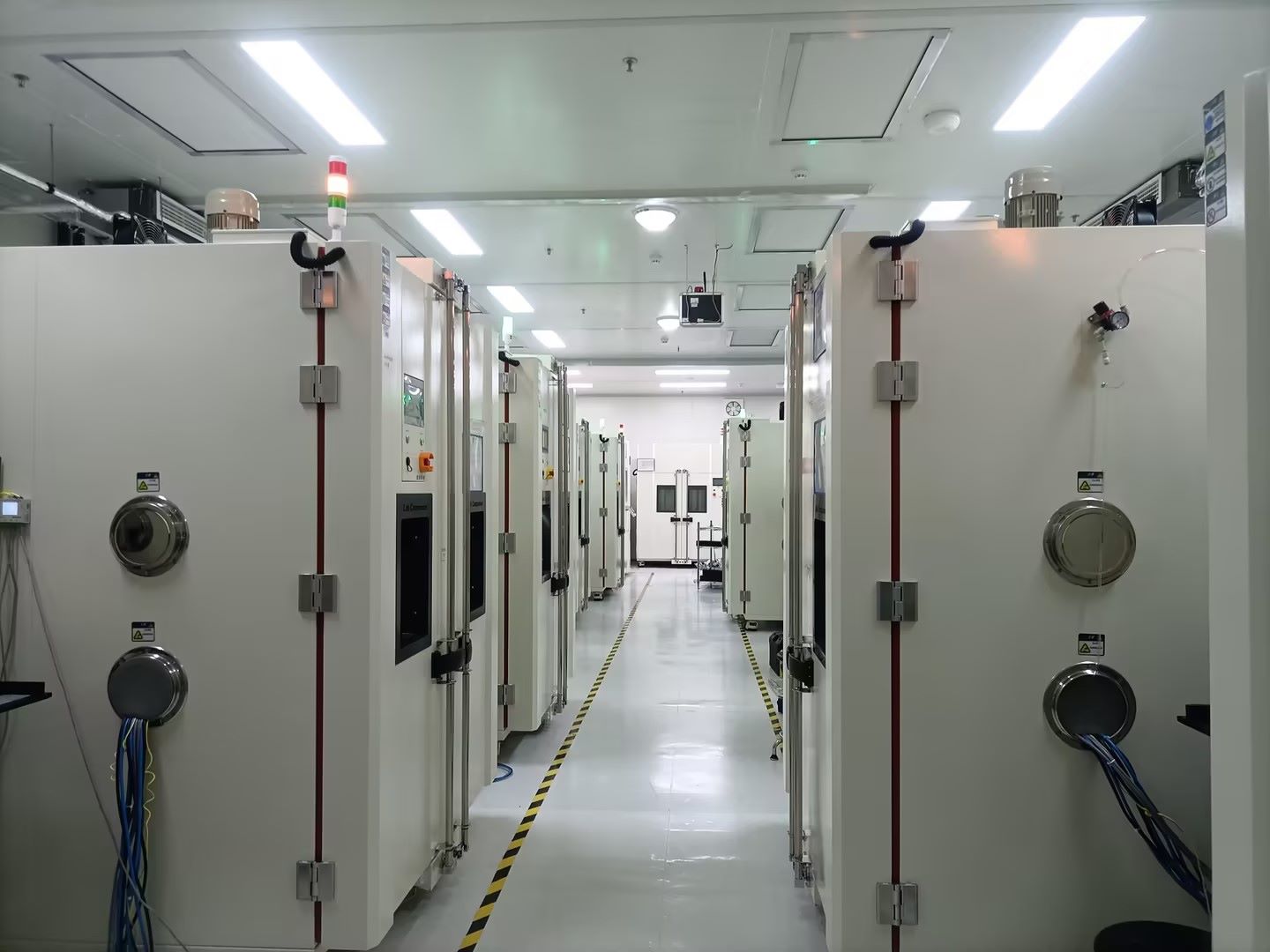
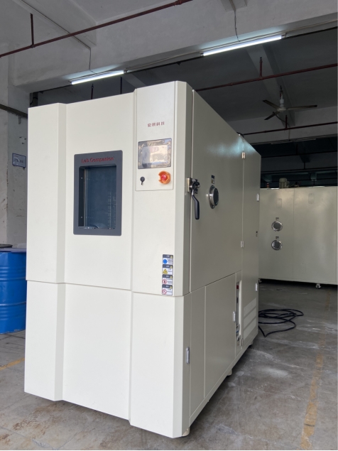
temperature cycle test chamber

First, let's talk briefly about optical communication. Some people also say that it is called optical communication, so they are two in the end is not a concept. In fact, they are two of the same concept. Optical communication is the use of optical signals for communication technology, and optical communication is based on optical communication, through optical devices such as optical fibers, optical cables to achieve data transmission. Optical communication technology is widely used, such as our daily use of fiber optic broadband, mobile phone optical sensors, optical measurement in aerospace and so on. It can be said that optical communication has become an important part of modern communication field. So why is optical communication so popular? In fact, it has many advantages, such as high-speed transmission, large bandwidth, low loss and so on.

Common optical communication products include: optical cable, fiber switch, fiber modem, etc., used to transmit and receive optical signals of optical fiber communication equipment; Temperature sensor, strain sensor, displacement sensor, etc., can measure various physical quantities in real time and other optical fiber sensors; Erbium-doped optical amplifier, erbium-doped ytterbium-doped optical amplifier, Raman amplifier, etc., used to expand the intensity of optical signals and other optical amplifiers; Helium-neon laser, diode laser, fiber laser, etc., are light sources in optical communication, used to produce high brightness, directional and coherent laser light and other lasers; Photodetectors, optical limiter, photodiodes, etc., for receiving optical signals and converting them into electrical signals and other optical receivers; Optical switches, optical modulators, programmable optical arrays, etc. are used to control and adjust optical signal transmission and routing and other optical controllers. Let's take mobile phones as an example and talk about the application of optical communication products on mobile phones:

1. Optical fiber: Optical fiber is generally used as a part of the communication line, due to its fast transmission speed, communication signals are not easily affected by external interference and other characteristics, has become an important part of mobile phone communication.

2. Photoelectric converter/optical module: photoelectric converter and optical module are devices that convert optical signals into electrical signals, and are also a very important part of mobile phone communication. In the era of high-speed communication such as 4G and 5G, the speed and performance of such equipment need to be continuously improved to meet the needs of fast and stable communication.

3. Camera module: In the mobile phone, the camera module generally includes CCD, CMOS, optical lens and other parts, and its quality and performance also have a significant impact on the quality of optical communication of the mobile phone.

4. Display: Mobile phone displays generally use OLED, AMOLED and other technologies, the principle of these technologies are related to optics, but also an important part of mobile phone optical communication.

5. Light sensor: Light sensor is mainly used in mobile phones for environmental light sensing, proximity sensing and gesture sensing, and is also an important mobile phone optical communication product.

It can be said that optical communication products fill all aspects of our life and work. However, the production and use environment of optical communication products is often changeable, such as high or low temperature weather environment when working outdoors, or the use of a long time will also encounter changes in thermal expansion and contraction. So how is the reliable use of these products achieved? That has to mention our protagonist today - rapid temperature change test chamber, also known as TC box in the optical communication industry. In order to ensure that optical communication products still work normally under various environmental conditions, it is necessary to carry out rapid temperature change tests on optical communication products. The rapid temperature change test chamber can simulate a variety of different temperature and humidity environments, and simulate instantaneous extreme environmental changes in the real world within a rapid range. So how is the rapid temperature change test chamber applied in the optical communication industry?

1. Optical module performance test: Optical module is a key component of optical communication, such as optical transceiver, optical amplifier, optical switch, etc. The rapid temperature change test chamber can simulate different temperature environments and test the performance of the optical module at different temperatures to evaluate its adaptability and reliability.

2. Reliability test of optical devices: optical devices include optical fibers, optical sensors, grating, photonic crystals, photodiodes, etc. The rapid temperature change test chamber can test the temperature change of these optical devices and evaluate their reliability and life based on the test results.

3. Optical communication system simulation test: The rapid temperature change test chamber can simulate various environmental conditions in the optical communication system, such as temperature, humidity, vibration, etc., to test the performance, reliability and stability of the entire system.

4. Technology research and development: The optical communication industry is a technology-intensive industry, which needs to constantly develop new technologies and new products. The rapid temperature change test chamber can be used to test the performance and reliability of new products, helping to accelerate the development and market of new products.

In summary, it can be seen that in the optical communication industry, the rapid temperature change test chamber is usually used to test the performance and reliability of optical modules and optical devices. Then when we use the rapid temperature change test chamber for testing, different optical communication products may require different standards. The following are rapid temperature change test standards for some common optical communication products:

1. Optical fiber: Common test standards There are common optical fiber rapid temperature change test standards are the following: IEC 61300-2-22: The standard defines the stability and durability test method of optical fiber components, section 4.3 of which specifies the thermal stability test method of optical fiber components, in the case of rapid temperature changes to the optical fiber components for measurement and evaluation. GR-326-CORE: This standard specifies reliability test requirements for fiber optic connectors and adapters, including thermal stability tests to assess the reliability of fiber optic connectors and adapters in temperature changing environments. GR-468-CORE: This standard defines the performance specifications and test methods for fiber optic connectors, including temperature cycle testing, accelerated aging testing, etc., to verify the reliability and stability of fiber optic connectors under various environmental conditions. ASTM F2181: This standard defines a method for fiber failure testing under high temperature and high humidity environmental conditions to evaluate the long-term durability of the fiber. And the above standards such as GB/T 2423.22-2012 are tested and evaluated for the reliability of optical fiber in rapid temperature changes or long-term high temperature and high humidity environments, which can help the majority of manufacturers to ensure the quality and reliability of optical fiber products.

2. Photoelectric converter/optical module: The common rapid temperature change test standards are GB/T 2423.22-2012, GR-468-CORE, EIA/TIA-455-14 and IEEE 802.3. These standards mainly cover the test methods and specific implementation steps of photoelectric converters/optical modules, which can ensure the performance and reliability of products in different temperature environments. Among them, the GR-468-CORE standard is specifically for the reliability requirements of optical converters and optical modules, including temperature cycle test, wet heat test and other environmental tests, requiring optical converters and optical modules to maintain stable and reliable performance in long-term use.

3. Optical sensor: The common rapid temperature change test standards are GB/T 27726-2011, IEC 61300-2-43 and IEC 61300-2-6. These standards mainly cover the test methods and specific implementation steps of the temperature change test of the optical sensor, which can ensure the performance and reliability of the product in different temperature environments. Among them, the GB/T 27726-2011 standard is the standard for the performance test method of optical sensors in China, including the environmental test method of optical fiber sensors, which requires the optical sensor to maintain stable performance in a variety of working environments. IEC 60749-15 standard is the international standard for the temperature cycle test of electronic components, and it also has reference value for the rapid temperature change test of optical sensors.

4. Laser: Common rapid temperature change test standards are GB/T 2423.22-2012 "Electrical and electronic products environmental test Part 2: Test Nb: temperature cycle test", GB/T 2423.38-2002 "Basic test methods for electrical components Part 38: Temperature resistance test (IEC 60068-2-2), GB/T 13979-2009 "Laser product Performance test method", IEC 60825-1, IEC/TR 61282-10 and other standards mainly cover the laser temperature change test method and specific implementation steps. It can ensure the performance and reliability of products in different temperature environments. Among them, the GB/T 13979-2009 standard is the standard for the performance test method of laser products in China, including the environmental test method of the laser under temperature changes, requiring the laser to maintain stable performance in a variety of working environments. The IEC 60825-1 standard is a specification for the integrity of laser products, and there are also relevant provisions for the rapid temperature change test of lasers. In addition, the IEC/TR 61282-10 standard is one of the guidelines for the design of optical fiber communication systems, which includes methods for the environmental protection of lasers.

5. Optical controller: The common fast temperature change test standards are GR-1209-CORE and GR-1221-CORE. GR-1209-CORE is a reliability standard for optical fiber equipment, mainly for the reliability test of optical connections, and specifies the reliability experiment of optical connection systems. Among them, the rapid temperature cycle (FTC) is one of the test projects, which is to test the reliability of optical fiber modules under rapidly changing temperature conditions. During the test, the optical controller needs to perform temperature cycling in the range of -40 ° C to 85 ° C. During the temperature cycle, the module should maintain normal function and not produce abnormal output, and the test time is 100 temperature cycles. GR-1221-CORE is a reliability standard for fiber optic passive devices and is suitable for the testing of passive devices. Among them, the temperature cycle test is one of the test items, which also requires the optical controller to be tested in the range of -40 ° C to 85 ° C, and the test time is 100 cycles. Both of these standards specify the reliability test of the optical controller in the environment of temperature change, which can determine the stability and reliability of the optical controller under harsh environmental conditions.

In general, different rapid temperature change test standards may focus on different test parameters and test methods, it is recommended to choose the corresponding test standards according to the use of specific products.

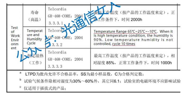
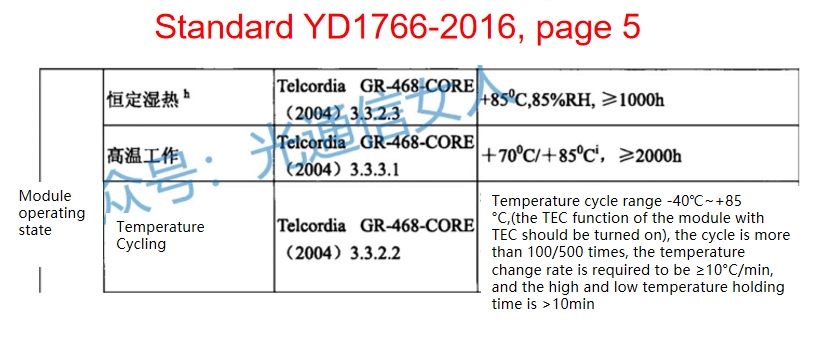
Recently, when we discuss the reliability verification of optical modules, there is a contradictory indicator, the number of temperature cycles of optical module verification, there are 10 times, and 20 times, 100 times, or even 500 times.

Frequency definitions in two industry standards:

The references to these standards have clear sources and are correct.

For the 5G forward optical module, our opinion is that the number of cycles is 500, and the temperature is set at -40 °C ~85 °C

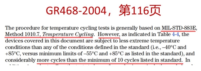
The following is the description of the 10/20/100/500 above in the original text of GR-468(2004)

Because of the limited space, this article introduces the use of rapid temperature change test chamber in the optical communication industry. If you have any questions when using rapid temperature change test chamber and other environmental test equipment, welcome to discuss with us and learn together.

IEC 60068-2 Combined Condensation and Temperature and Humidity Test

IEC 60068-2 Combined Condensation and Temperature and Humidity Test

In the IEC60068-2 specification, there are a total of five kinds of humid heat tests. In addition to the common 85℃/85%R.H., 40℃/93%R.H. fixed-point high temperature and high humidity, there are two more special tests [IEC60068-2-30, IEC60068-2-38], they are alternating wet and humid cycle and temperature and humidity combined cycle, so the test process will change temperature and humidity. Even multiple groups of program links and cycles applied in IC semiconductors, parts, equipment, etc. To simulate the outdoor condensation phenomenon, evaluate the material's ability to prevent water and gas diffusion, and accelerate the product's tolerance to deterioration, the five specifications are organized into a comparison table of the differences in the wet and heat test specifications, and the main points of the test are explained in detail for the wet and heat combined cycle test, and the test conditions and points of GJB in the wet and heat test are supplemented.

High and Low Temperature Humidity Test Chamber

IEC60068-2-30 alternating humid heat cycle test

Note: This test uses the test technique of maintaining humidity and temperature alternations to make moisture permeate into the sample and produce condensation (condensation) on the surface of the product to confirm the adaptability of the component, equipment or other products in use, transportation and storage under the combination of high humidity and temperature and humidity cycle changes. This specification is also suitable for large test samples. If the equipment and the test process need to keep the power heating components for this test, the effect will be better than IEC60068-2-38, the high temperature used in this test has two (40 °C, 55 °C), the 40 °C is to meet most of the world's high temperature environment, while 55 °C meets all the world's high temperature environment, the test conditions are also divided into [cycle 1, cycle 2], In terms of severity, [Cycle 1] is higher than [Cycle 2].

Suitable for side products: components, equipment, various types of products to be tested

Test environment: the combination of high humidity and temperature cyclic changes produces condensation, and three kinds of environments can be tested [use, storage, transportation ([packaging is optional)]

Test stress: Breathing causes water vapor to invade

Whether power is available: Yes

Not suitable for: parts that are too light and too small

Test process and post-test inspection and observation: check the electrical changes after moisture [do not take out the intermediate inspection]

Test conditions: humidity: 95% R.H. warming] after [humidity maintain (25 + 3 ℃ low temperature - - high temperature 40 ℃ or 55 ℃)

Rising and cooling rate: heating (0.14℃/min), cooling (0.08~0.16℃/min)

Cycle 1: Where absorption and respiratory effects are important features, the test sample is more complex [humidity not less than 90%R.H]

Cycle 2: In the case of less obvious absorption and respiratory effects, the test sample is simpler [humidity is not less than 80%R.H.]

IEC60068-2-30 Alternating temperature and humid test (condensation test)

Note: For component types of parts products, a combination test method is used to accelerate the confirmation of the test sample's tolerance to degradation under high temperature, high humidity and low temperature conditions. This test method is different from the product defects caused by respiration [dew, moisture absorption] of IEC60068-2-30. The severity of this test is higher than that of other humid heat cycle tests, because there are more temperature changes and [respiration] during the test, and the cycle temperature range is larger [from 55℃ to 65℃]. The temperature variation rate of the temperature cycle also becomes faster [temperature rise :0.14℃/min becomes 0.38℃/min, 0.08℃/min becomes 1.16 ℃/min]. In addition, different from the general humid heat cycle, the low temperature cycle condition of -10℃ is increased, which accelerates the breathing rate and makes the water condensing in the gap of the substitute icing. Is the characteristic of this test specification, the test process allows power and load power test, but can not affect the test conditions (temperature and humidity fluctuation, rising and cooling rate) because of the heating of the side product after power, due to the change of temperature and humidity during the test process, but the top of the test chamber can not condenses water droplets to the side product.

Suitable for side products: components, metal components sealing, lead end sealing

Test environment: combination of high temperature, high humidity and low temperature conditions

Test stress: accelerated breathing + frozen water

Whether it can be powered on: it can be powered on and external electric load (it can not affect the conditions of the test chamber because of power heating)

Not applicable: Can not replace moist heat and alternating humid heat, this test is used to produce defects different from respiration

Test process and post-test inspection and observation: check the electrical changes after moisture [check under high humidity conditions and take out after test]

Test conditions: damp temperature and humidity cycle (25 ↔ 65 + 2 ° C / 93 + 3% r.h.) - low temperature cycle (25 ↔ 65 + 2 ℃ / 93 + 3% r.h. -- 10 + 2 ° C) X5 cycle = 10 cycle

Rising and cooling rate: heating (0.38℃/min), cooling (1.16 °C/min)

GJB150-o9 humid heat test

Description: The wet and heat test of GJB150-09 is to confirm the ability of equipment to withstand the influence of hot and humid atmosphere, suitable for equipment stored and used in hot and humid environment, equipment prone to high humidity storage or use, or equipment may have potential problems related to heat and humidity. Hot and humid locations may occur throughout the year in tropical areas, seasonal occurrences in mid-latitudes, and in equipment subjected to comprehensive changes in pressure, temperature and humidity. The specification specifically emphasizes 60 ° C /95%R.H. This high temperature and humidity does not occur in nature, nor does it simulate the humid and thermal effect after solar radiation, but it can find potential problems in the equipment. However, it is not possible to reproduce complex temperature and humidity environments, assess long-term effects, and reproduce humidity effects associated with low humidity environments.

High and Low Temperature Humidity Test Chamber